Winter campaign at Cook Haven, Sol 3512 - 3599 (December 13, 2013 - March 10, 2014) |

  |
Winter campaign at Cook Haven, Sol 3512 - 3599 (December 13, 2013 - March 10, 2014) |
 Jan 27 2014, 12:03 AM Jan 27 2014, 12:03 AM
Post
#121
|
||
|
Solar System Cartographer  Group: Members Posts: 10158 Joined: 5-April 05 From: Canada Member No.: 227 |
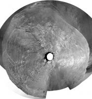
And this, by tilting the projection plane and shrinking radially, puts the area in more of a map-like geometry.
Phil
-------------------- ... because the Solar System ain't gonna map itself.
Also to be found posting similar content on https://mastodon.social/@PhilStooke Maps for download (free PD: https://upload.wikimedia.org/wikipedia/comm...Cartography.pdf NOTE: everything created by me which I post on UMSF is considered to be in the public domain (NOT CC, public domain) |
|
 |
 
|
|
|
Jan 27 2014, 09:24 AM
Post
#122
|
|
 Senior Member Group: Moderator Posts: 2262 Joined: 9-February 04 From: Melbourne - Oz Member No.: 16 |
The first of Phil's polar images gives a real sense of the slope Oppy is on. Staring at it in my half awake Monday morning state, I get a real feeling that I may fall off the top of the rover and roll down Solander Point.
 
-------------------- |
|
|
|
|
Jan 28 2014, 10:44 PM
Post
#123
|
|
|
Member Group: Members Posts: 866 Joined: 15-March 05 From: Santa Cruz, CA Member No.: 196 |
|
|
|
|
|
Feb 4 2014, 03:23 PM
Post
#124
|
|
 Senior Member Group: Members Posts: 4247 Joined: 17-January 05 Member No.: 152 |
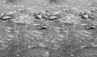
After a short bump downhill we finally have a view of what was under the rover:
http://qt.exploratorium.edu/mars/opportuni...0M1.JPG?sol3566 Pinnacle Island is the small rock just above the left edge of the sundial. We can now see a messed-up area farther uphill that looks like a potential source for PI. |
|
|
|
|
Feb 4 2014, 08:02 PM
Post
#125
|
|||
|
Senior Member Group: Members Posts: 2823 Joined: 22-April 05 From: Ridderkerk, Netherlands Member No.: 353 |
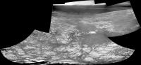
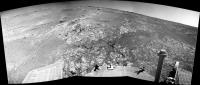
Here is the panoramic view stitched together from L0 Navcam images
taken on Sol 3559-3560 and Sol 3564. Jan van Driel
and Sol 3566
|
||
|
|
|
||
|
Feb 4 2014, 09:36 PM
Post
#126
|
|
|
Senior Member Group: Members Posts: 3516 Joined: 4-November 05 From: North Wales Member No.: 542 |
It's clear from examples like Pinnacle Island, the deliberate crushing of gypsum veins at Cape York, Spirit's serendipitous discovery of silica and other examples that rover wheels are valuable geological tools in their own right, so I have a question for the engineers (including armchair engineers). How might you modify wheel design to maximise this function? Add a thin outstanding flange somewhere in the otherwise wide flattish tread profile perhaps? Have occasional small cup-shaped scoops or spikes at intervals around the wheel perimeter? Extra cameras? Any ideas?
|
|
|
|
|
Feb 4 2014, 10:08 PM
Post
#127
|
|
 Member Group: Members Posts: 404 Joined: 5-January 10 Member No.: 5161 |
QUOTE (ngunn @ Feb 4 2014, 01:36 PM)  ...rover wheels are valuable geological tools in their own right... I've always wondered if a rake has ever been considered, one that can be routinely dragged when roving over promising terrain, just enough to turn over some rocks and stir things up for a better idea of what the dust layers are hiding. Extra science could be had by taking advantage of the routine long drives, by dropping a rake at intervals just behind the rover, followed by a some pictures, and dragging would be well within the capabilities of the wheels. In case the device got stuck in the down position, some explosive bolts could get rid of it! |
|
|
|
|
Feb 5 2014, 01:36 PM
Post
#128
|
|
|
Forum Contributor Group: Members Posts: 1372 Joined: 8-February 04 From: North East Florida, USA. Member No.: 11 |
There are probably 50 engineering reasons why that is a bad idea, lol.
|
|
|
|
|
Feb 5 2014, 02:01 PM
Post
#129
|
|
|
Solar System Cartographer Group: Members Posts: 10158 Joined: 5-April 05 From: Canada Member No.: 227 |
The rake idea is pretty much what Spirit did when it was dragging a frozen wheel - digging a trench in the soil (making major discoveries as it did so, salty soils and silica) or moving small rocks. So basically that could be recreated at will by driving five wheels and not driving the sixth, without adding the complications and mass of a rake and the mechanisms needed to raise, lower and eject it.
Phil -------------------- ... because the Solar System ain't gonna map itself.
Also to be found posting similar content on https://mastodon.social/@PhilStooke Maps for download (free PD: https://upload.wikimedia.org/wikipedia/comm...Cartography.pdf NOTE: everything created by me which I post on UMSF is considered to be in the public domain (NOT CC, public domain) |
|
|
|
|
Feb 5 2014, 02:49 PM
Post
#130
|
|
 Senior Member Group: Members Posts: 3419 Joined: 9-February 04 From: Minneapolis, MN, USA Member No.: 15 |
There are a number of different configurations you could use for a rake-like implement off of a rover, though. A large flap-like rake would serve to disinter buried rocks and pebbles, at the cost of possibly getting hung up and also of piling up large mounds of dirt. However, a dixie-cup-sized device, open at one end and with a mesh at the other, could be used to collect cobble-sized samples which are shallow-buried for a sample return mission.
For in-situ analysis, you would need to identify a need to disinter buried cobbles as part of your sampling methodology for this kind of device to become important. For example, if you come up with a theory that only buried rocks will display a given desired-to-observe chemistry, you might want to develop a way of disinterring such rocks for easy transport to your sensors. I get the gut feeling that such a sampling methodology would be more useful for sample caching in preparation for a sample return mission than for in-situ analysis. But in either case, I'd think you would need a compelling reason for wanting access to shallow-buried rocks before getting into the complexities of designing such a raking mechanism. -the other Doug -------------------- The trouble ain't that there is too many fools, but that the lightning ain't distributed right. -Mark Twain
|
|
|
|
|
Feb 5 2014, 02:59 PM
Post
#131
|
|
|
Senior Member Group: Members Posts: 2346 Joined: 7-December 12 Member No.: 6780 |
A wheel with a partially sandpaper-like surface may be usable for an on-the-fly rock abrasion.
Edit: E.g. round patches on a wheel; rock could be abraded by steering in-place to the left and right. |
|
|
|
|
Feb 5 2014, 03:36 PM
Post
#132
|
|
|
Founder Group: Chairman Posts: 14432 Joined: 8-February 04 Member No.: 1 |
We have the RAT ( on MER ) and DRT ( on MSL ) for that. Using a wheel for it would be a messy affair.
And with all the notions of a 'rake'....you have to consider what would you take off MSL or MER to make room for it in terms of mass, volume, power..and budget. Such notions are not free...and you have to consider the cost to the vehicle. The wheels do a great job when required for simple trenching, crude abrasion....and at the same time are useful for getting around. Extra hardware really isn't justified. |
|
|
|
|
Feb 5 2014, 05:16 PM
Post
#133
|
|
|
Member Group: Members Posts: 866 Joined: 15-March 05 From: Santa Cruz, CA Member No.: 196 |
I had always wondered what kinds of pressures could be exerted using the arm, for instance to move a rock, perhaps the RAT would be the most appropriate contact point, my thought is that it would seem possible of being useful, though clearly such purpose was not designed in and re-purposing the existing assembly to do so is evidently fraught with unacceptable risk. I assume some thought went into this general concept for MSL, if not MER, though apparently not chosen as a route worth pursuing..
|
|
|
|
|
Feb 5 2014, 05:32 PM
Post
#134
|
|
|
Founder Group: Chairman Posts: 14432 Joined: 8-February 04 Member No.: 1 |
You enter a world of many many unknowns when you start trying to shove things around. Will it move at the toque the arm can handle - will something roll back and put torque on the system etc etc.
http://www-robotics.jpl.nasa.gov/publicati..._2005_final.pdf has some good IDD spec - including typical preload forces on the RAT of around 30N. The IDD is a very fragile thing. The Phoenix arm was a brute of a thing that could really bring some torque to the game, MSL's is about inbetween I believe. |
|
|
|
|
Feb 5 2014, 10:10 PM
Post
#135
|
|
|
Member Group: Members Posts: 866 Joined: 15-March 05 From: Santa Cruz, CA Member No.: 196 |
Thanks for finding that. very illuminating of the ingenuity involved in solving the myriad dilemmas and giving us 5mm positioning accuracy.
a favorite highlight (p4): "The mass allocation for the IDD of 4.4 kg, including launch restraints and cabling, was also an extreme design driver. The cabling mass alone, mostly to support instruments, was almost 1 kg. The arm had to support a turret of instruments with a mass of 2 kg, provide preload for the RAT, and be capable of achieving the absolute and repeatable positioning requirements described in Section 2. The mass allocated and load magnifications possible with the 5 DOF robot arm did not allow the structure and joints to be designed in such a way that the arm could not damage itself in all possible operational cases. Instead, an approach which integrated flight software fault protection, operational constraints, and mechanical capability was developed that reduced the risk of damaging the IDD during normal operations. Joint flexibility became particularly important since arm configurations that cause dangerous load magnifications also allow for significant travel past the point of instrument contact before the loads reach their critical stage. A redundant method of terminating IDD motion based on contact sensor feedback and tight limits on over travel past the expected contact point keep the arm in the safe load zone. While the torque used to get the joints started is capable of creating unsafe loads, software quickly ramps the current limit down after movement starts before more movement occurs than arm flexibility can accommodate. Software also limits the torque of the motors when the arm is in configurations that can magnify loads." |
|
|
|
|

|
Lo-Fi Version | Time is now: 5th May 2024 - 07:50 AM |
|
RULES AND GUIDELINES Please read the Forum Rules and Guidelines before posting. IMAGE COPYRIGHT |
OPINIONS AND MODERATION Opinions expressed on UnmannedSpaceflight.com are those of the individual posters and do not necessarily reflect the opinions of UnmannedSpaceflight.com or The Planetary Society. The all-volunteer UnmannedSpaceflight.com moderation team is wholly independent of The Planetary Society. The Planetary Society has no influence over decisions made by the UnmannedSpaceflight.com moderators. |
SUPPORT THE FORUM Unmannedspaceflight.com is funded by the Planetary Society. Please consider supporting our work and many other projects by donating to the Society or becoming a member. |
|